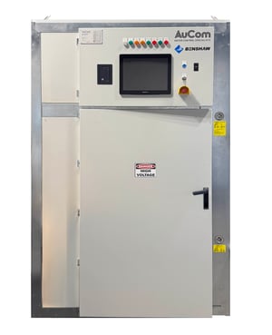
Skip to content
mve l-panel hero_rgb-2

L-Series MV Panel

  Amps 1 1  <2500A    Volts 1 1 2.3 - 15kV

The Versatile MV Panel System

The L-Series MV Panel System offers flexibility for a range of applications. L-Series panels can be deployed in either standalone or lineup configurations.

MVE L Series Panel

Highlights

Safety Icon-01
Complete

With models suitable for currents up to 1700A and voltages up to 13.8kV L-MVE starters have your motor control needs covered.

Modular Icon
Safe

Includes safety interlocks, protections and are Arc Fault Rated to ensure operators safety.

compact size icon-01
Highly Configurable

Switchgear options to suit your site including, Line and bypass breakers, isolation and earthing switches, PFC and fuses.

Flexible Design Icon-01
Standalone or Lineups

A range of options to suit your situation.

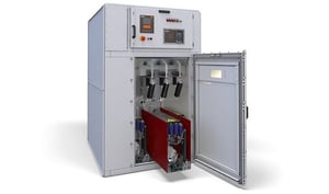
Features & Accessories

X-Series Callouts-01


 A Busbars - Air isolated, Tinned Copper, Short Circuit Rating 31.5/4 sec
 B Arc Blast Flap - 1 for each chamber
 C LV Cable Connection
 D Integrate Soft Starter & Drives on common bus
 E Safe LV Compartment - Arc Flash
 F Main Switching device - Manual or automatic control racking
 G Compact Width - 650mm to 1000mm
 H Hinged Door Panels - Mechanical interlocks, Two step door locking
 I Viewing Window

Specifications

General
Current Range 70 - 1700 A

Supply
Mains Voltage (L1, L2, L3)
   MVE-xxxx-V02 2.3 kV Phase-phase
   MVE-xxxx-V04 4.2 kV Phase-phase
  MVE-xxxx-V06 6.6 kV Phase-phase
  MVE-xxxx-V11 10/11 kV Phase-phase
  MVE-xxxx-V13 13.2-13.8 kV Phase-phase
Control Voltage (A1, A2, A3) 85 ~ 264 VAC or 90 ~ 350 VDC*
Rated Frequency 50/60 Hz
Rated lightning impulse withstand voltage (Up)  
  2.3 - 6.6 kV
60 kV
  10/11 kV
75 kV
  13.2/13.8 kV
95 KV
Rated short-time withstand current (symmetrical RMS) (lk) 50 kA**
 
Short Circuit Capability
Current Range 24 A ~ 1250 A (nominal)
Motor connection In-line or inside delta
Bypass Integrated internal
 
ANSI Protection Codes
Code Description Built-in Protection
48 Maximum start time Excess start time
66 Too many starts Restart delay and dynamic thermal model
37 Undercurrent Undercurrent
51L Load Increase (alarm) High current frequency output
51R Overcurrent - jam Excess start time, electronic shearpin
50 Overcurrent - short  Shorted SCR, electronic shearpin
49/51 Thermal overload Thermal overload - dynamic model
46 Current imbalance Current imbalance
27 Undervoltage Undervoltage
59 Overvoltage Overvoltage
47 Phase loss Phase loss
47 Phase sequence Phase sequence
50G Ground fault Ground fault
85 Communications failure Communications failure
85 Internal failure Internal failure
94/95

Ext. fault 1/code-1

Auxiliary trip A

Ext. fault 1/code-2

Auxiliary trip B
23

Motor overtemperature

Thermistor protection*
49

Stator winding overtemperature

Thermistor protection*
32

Under power

Power Loss


Show more
Configuration

DOL Starters

  • Direct online starting
  • Motor protection replays
  • RTD Modules
  • Fusing
  • Power Factor Capacitors
  • PLC logic
DOL-Diagram-03 (1)
Configuration

Star/Delta Starters

  • Star/Delta starting
  • Motor protection replays
  • RTD Modules
  • Fusing
  • Power Factor Capacitors
  • PLC logic
Star-Delta-Diagram-01
Configuration

Auto Transformer Starter (ATS)

  • Autotransformer starting
  • Motor protection replays
  • RTD Modules
  • Fusing
  • Power Factor Capacitors
  • PLC logic
ATS-Diagram-02 (1)
Configuration

Heater Controller

AuCom's MV Heater Controller, built for high-temperature systems up to 11kV, is a fully integrated solution that enhances heater life, cuts installation costs, and removes the need for step-down transformers. Designed to meet strict safety standards, it offers a reliable, space-saving alternative for transitioning to clean, electric heating.
Heater Controller-2

Specifications

Fully type tested

AuCom L-Series panels are fully type tested according to IEC 62271-200:

  • Short time withstand current
  • Peak withstand current
  • Internal arc fault (IAC Classification: AFL 31.5 kA for 1 second)
  • Dielectric test on main auxiliary circuits
  • IP rating
  • Temperature rise tested to 50°C ambient temperature and main circuit resistance

L-Series Panel Specifications

  • Rated voltage: 3.6 kV - 17.5 kV
  • Rated busbar current: Up to 2000 A
  • Rated short time withstand current/peak: Up to 40 kA for 1 second / 104 KA
  • Internal arc fault IAC classification:
    AFL 31.5 kA for 1 second
  • Partition classification: PM
  • Loss of service continuity:
  • LSC1/LSC2/LSC2B
  • IP4X protection rating (IP54 optional)
  • Altitude: < 1000 m [higher with derating]
  • Ambient temperature: -10 °C -60 °C (above 50 °C with derating)
  • Colour painting: RAL7035 (other colours optional)