


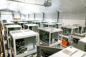
MCCs & Distribution Panels
Custom LV Panels
- DOL Starters
- Star/Delta Starters
- Soft Starters
- Drives
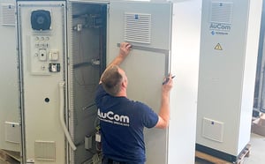
Custom MV Panels
- DOL Starters
- Star/Delta Starters
- Auto Transformer Starters (ATS)
- Heater Controllers
- PFC
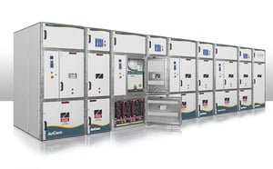
Personnel Safety Prioritised
- DOL Starters
- Smart DOL Starters
- Soft Starters
- Power Distribution
Frequently Asked Questions
Here are answers to some of the most commonly asked questions about Motor Control Centres (MCCs) and Distribution Panels, to help you better understand their functionality, applications, and benefits.
IEC 60529 specifies protection ratings for enclosures. These ratings describe the level of protection against dust and liquids entering the enclosure.
IP ratings consist of two numbers. The first number describes the protection against solid objects and the second number describes the level of protection against entry of liquids.
| IP | Solids | Liquids |
| 0 | No protection. | No protection. |
| 1 | Protected against solid objects greater than 50 mm (eg accidental touching by hand). | Protected against vertically falling drops of water (eg condensation). |
| 2 | Protected against solid objects greater than 12.5 mm (eg fingers). | Protected against direct sprays of water up to 15° from vertical. |
| 3 | Protected against solid objects greater than 2.5 mm (eg tools or wires). | Protected against sprays of water up to 60° from vertical. |
| 4 | Protected against solid objects greater than 1 mm (eg tools and small wires). | Limited protection against water sprayed from all directions (limited ingress permitted). |
| 5 | Limited protection against dust (some ingress but no harmful deposit). | Limited protection against low pressure jets of water from all directions (limited ingress permitted). |
| 6 | Complete protection against dust. | Protected against strong jets of water (limited ingress permitted). |
| 7 | Protected against the effects of immersion in water between 15 cm and 100 cm. | |
| 8 | Protected against extended immersion in water under pressure. |
NEMA 250 is a product standard that addresses many aspects of enclosure design and performance.
| NEMA | Protection against solid objects | Closest IP equivalent* |
| 1 | Indoor, protection from contact. | IP 20 |
| 2 | Indoor, limited protection from dirt and water. | IP 22 |
| 3 | Outdoor, some protection from rain, sleet, windblown dust and ice. | IP 55 |
| 3R | Outdoor, some protection from rain, sleet and ice. | IP 24 |
| 4 | Indoor or outdoor, some protection from windblown dust, rain, splashing water, hose-directed water and ice. | IP 66 |
| 4X | Indoor or outdoor, some protection from corrosion, windblown dust, rain, splashing water, hose-directed water and ice. | IP 66 |
| 6 | Indoor or outdoor, some protection from ice, hose-directed water, entry of water when submerged at limited depth. | IP 67 |
| 12 | Indoor, protection from dust, falling dirt and dripping non-corrosive liquids. | IP 54 |
| 13 | Indoor, protection from dust, spraying water, oil and non-corrosive liquids. | IP 54 |
*NEMA and IP ratings are not directly equivalent and this information provides an approximate correlation only.
- compartment types
- method of access to compartments
- safety levels provided during access
- effect on continuation of service during access
- type of insulation barriers between compartments
- internal arc endurance (refer to section on internal arc classification)
The manufacturer must state which areas of the switchgear are accessible and provide a clearly defined switchgear classification
| Types of compartments with regard to accessibility | Features | |
| Operator-accessible compartment | Interlocked-based accessible compartment. Intended to be opened for normal operation and maintenance | No tools for opening - Interlocking allowing access only when HV parts are dead and earthed |
|
Procedure-based accessible compartment. Intended for normal operation and maintenance. |
No tools for opening - Provision for locking to be combined with operator procedures, to allow access only when HV parts are dead and earthed | |
| Tool-based accessible compartment. Possible for user to open, but not intended to be for normal operation and maintenance. | Tools necessary for opening. No specific provision to address access procedure. Special procedures may be required to maintain performances. | |
| Not possible for user to open (not intended to be opened) | Opening destroys compartment or clear indication to the user. Accessibility not relevant. | |
| Switchgear classification with regard to the loss of service continuity when opening accessible compartments | Features | |
| LSC1 | Other functional units or some of them shall be disconnected | |
| LSC2 | LSC2A | Other functional units can be energized |
| LSC 2B | Other functional units and all cable compartments can be energized | |
| Switchgear classification with regard to the nature of the barrier between live parts and opened accesible compartment | Features | |
| PM | Metallic shutters and partition between live parts and open compartment - (metal-enclosed condition maintained) | |
| PI | Insulation-covered discontinuity in the metallic partitions/shutters between live parts and open compartment. | |
| Switchgear classification with regard to mechanical, electrical and fire hazards in case of internal arc during normal operation | Features | |
| IAC | No ejection of parts, no ignitions of cloths, enclosure remains earthed | |
Switchgear is rated according to IEC 62271-1. When choosing switchgear, its rating must be sufficient for the electrical characteristics at the point of installation, the environmental conditions it needs to operate under, and the safety requirements. Future expansion of the switchgear distribution system needs to be considered, as this may affect initial rating requirements.
Switchgear selection is determined by considerations including:
Electrical conditions
- System operating voltage (U)
- System operating frequency (f)
- Nominal operating current (I)
- Short circuit current levels at the point of installation (ISC, Idyn, etc)
- Horizontal busbar arrangement
Environmental conditions
- Ambient temperature
- Altitude
- Pollution degree
- Indoor or outdoor installation
Personnel safety considerations
- Internal Arc Classification (IAC)
- Interlocking of access areas and switchgear apparatus
- Access method (e.g. tools, keys, process, etc.)
- Withdrawable switchgear apparatus
ANSI defined switchgear is equivalent to IEC classification LSC2B-PM, with the following characteristics:
- the main switching device is withdrawable, with disconnecting auxiliary control circuits
- separate compartments are provided for voltage transformers and control transformers
- busbar compartments are divided between adjacent enclosures
- metal barriers isolate the withdrawable compartment, when the main switching device is drawn-out into test position
- main circuit busbars and connections are covered with fire resistant insulating material
- mechanical interlocking prevents the withdrawable switching device from being moved into service position
- low voltage control parts are segregated from medium voltage apparatus
- all voltage transformers must have primary circuit current limiting fuses
Interlocking between different switchgear apparatus and enclosure access covers and doors enhances personnel
safety, as well as improving operational convenience. If a switching device can cause serious damage in an incorrect
position, this must also have a locking facility.
Interlocking uses electrical and mechanical methods or a combination of both.
IEC 62271-200 states mandatory rules for switchgear interlocking:
For metal-enclosed switchgear with removable switching apparatus:
- the switching device must be in the open position before it can be withdrawn
- the switching device can only be operated in the positive service or test position
- the switching device cannot be closed unless the auxiliary control circuits required to open the switch are connected. Auxiliary control circuits cannot be disconnected with the switching device closed in the
service position
For metal-enclosed switchgear with disconnectors:
- a disconnector cannot be operated under conditions other than those for which it is intended to be used
- a disconnector cannot be operated unless the main switching device is open
- operation of a main switching device is prevented unless its associated disconnector is in a positive service, test or earth position
- disconnectors providing isolation for maintenance and servicing must have a locking facility
Metal enclosed switchgear can suffer internal faults at numerous locations, causing a wide range of physical damage.
Internal Arc Classification (IAC) of metal enclosed switchgear considers the damage that can affect covers, doors, inspection windows, ventilation openings etc, as a result of overpressure within panel compartments. IAC also takes into consideration damage from thermal effects, ejected hot gases and molten particles.
When selecting metal enclosed switchgear, the probability of internal arcing and the safety risk to operators and the
general public needs to be considered. Where the safety risk is considered relevant, the switchgear should be IAC classified. The IAC classification indicates the maximum fault current level and duration to which the switchgear has been tested. When choosing switchgear, the IAC rating should exceed the expected fault current level and duration at the point of installation.
The rating also takes into account the accessibility of the switchgear. IAC tested and certified switchgear must always be clearly marked with the classification, fault level and duration, and accessibility of each side.
The primary standard for internal arc classification of medium voltage metal enclosed switchgear is IEC 62271-200;
IEC 62271-202 is also relevant.
IEC 62271-200 details test procedures to assess damage to switchgear from internal arcing. Test results provide the
switchgear with an IAC classification. Switchgear which passes indoor testing is also considered suitable for outdoor
use with the same accessibility requirements.
Accessibility is divided into two categories, Type A is for authorised personnel dressed with adequate protective equipment and Type B for general public access. Equipment is also tested for different directions of access: front,
rear or lateral (side).
Cotton cloth indicator panels are placed 2 m above ground level and on each accessible side of the equipment under test. If pressure relief ducts are part of the switchgear design, these must also be subjected to cloth indicator panel testing.
Tests are carried out by supplying a predetermined level of fault current for a specific duration. Using various test
procedures, the applied fault current creates an internal arc to ground within a specific region of the switchgear. In
general, test results are considered acceptable if:
- correctly secured doors and covers do not open - deformation is acceptable, providing it doesn't protrude as far as the indicator panels
- no fragmentation of the enclosure occurs within the test time - small particles up to 60 g are acceptable
- arcing does not cause any holes in the accessible areas, up to a height of 2 metres
- indicator panels do not ignite due to hot gas emissions
- the enclosure remains connected to its earth point (verified by a continuity test)
There are many potential causes for internal arcing within metal enclosed switchgear. Some of the more common causes are:
- foreign matter in the enclosure (eg vermin, metal swarf, tools)
- contamination and general degradation of insulation material
- inadequate insulation of cable terminations
- overheating of termination points due to inadequate preparation and tightening
- system overvoltage
- incorrect protection settings and coordination
| Locations where internal faults are most likely to occur | Possible causes of internal faults | Examples of preventative measures |
| Cable compartments | Inadequate design |
Selection of adequate dimensions Use of appropriate materials |
| Faulty installation | Avoidance of crossed cables connections. Checking of workmanship on site. Correct torque. | |
| Failure of solid or liquid insulation (defective or missing) |
Checking of workmanship and/or dielectric test on site. Regular checking of liquid levels, where applicable |
|
| Disconnectors Switches Earthing switches |
Maloperation | Interlocks. Delayed reopening. Independent manual operation. Making capacity for switches and earthing switches. Instructions to personnel. |
|
Bolted connections and contacts |
Corrosion | Use of corrosion inhibiting coating and/or greases. Use of plating. Encapsulation, where possible. |
| Faulty assembly | Checking of workmanship by suitable means. Correct torque. Adequate locking means. |
|
| Ferro-resonance | Avoidance of these electrical influences by suitable design of the circuit. |
|
| Instrument transformers | Short circuit on LV side for VTs | Avoid short circuit by proper means for example, protection cover, LV fuses. |
| Circuit breakers | Insufficient maintenance | Regular programmed maintenance. Instructions to personnel. |
| All locations | Error by personnel | Limitation of access by compartmentation. Insulation embedded live parts. Instructions to personnel. |
| Ageing under electric stresses | Partial discharge routine tests. | |
| Pollution, moisture, ingress of dust, vermin, etc |
Measures to ensure that the specified service conditions are achieved. Use of gasfilled compartments. |
|
| Overvoltages | Surge protection. Adequate insulation co-ordination. Dielectric tests on site. |
Certain design techniques are used to provide a high level of safety to personnel, by minimising the effects of internal
arcing:
- compartmenting of enclosure
- pressure relief methods
- double skin panels
- arc venting away from access areas
- remote control of switchgear
- rapid fault clearance
Rapid fault clearance requires fast detection and isolation of the arc. This can be achieved using:
- light, heat or pressure sensors combined with a relay to trip a fast acting circuit breaker
- pressure operated earth switch capable of diverting the internal arc to ground (arc eliminator)
- fast acting, current limiting line supply fuses