


Variable Frequency Drives (VFDs)
AuCom’s variable frequency drives (VFDs) provide precise motor control across a wide range of low and medium voltage applications. Built for reliability and performance, our drives support systems operating up to 13.8kV, delivering efficiency and flexibility to meet your operational needs.
VFDs enable you to adjust motor speed to match the exact demands of your process, making them ideal for industries such as mining, manufacturing, HVAC, and water and wastewater treatment. By optimising motor performance, VFDs also provide one of the most energy-efficient solutions for variable speed applications.
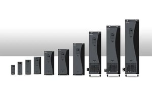
| 4 - 450kW | 380 - 460V |
Compact, efficient and powerful. H1 Series Drives support multiple motor types with advanced vector control, energy-saving features, and space-saving book-type design.
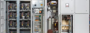
| 55 - 4000kW | 380 - 690V |
AuCom AFE Drives deliver low harmonic distortion and energy recovery in a compact, all-in-one design. Available in air or liquid cooling, the modular AFE platform ensures reliable, high-efficiency performance up to 4000 kW.
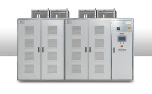
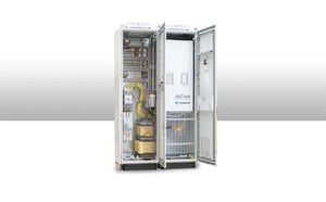
MVH2.0 Drive
| 315 - 25,000kW | 2.3 - 13.8kV |
The MVH2.0 delivers advanced performance, reliability, and intelligent control for demanding MV applications. With multilevel CHB technology, cloud-based monitoring, and scalable enclosures, it’s compact, connected, and built to perform.