
H1 Series LV VFD
9 - 820A
4 - 450kW
380 - 460V
Multi-purpose Low-Voltage VFDs
With a power range of 9-820 A, 4-450 kW and 380-460 V, they are perfect for many industrial applications.
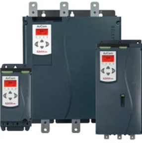
These versatile and highly efficient multi-drives are user-friendly, reliable and environmentally friendly. In addition, they have a book-type design in combination to an independent vertical air duct for heat dissipation, so they can be installed side by side. Our H1 series offers excellent drive performance and control functionality with a small footprint and high power density.

Highlights
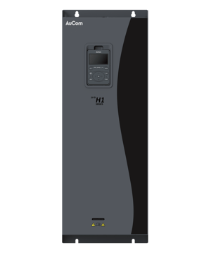
Our H1 Series features a book-type design with an independent vertical air duct for efficient heat dissipation and side-by-side installation to save space. Its narrow-body scheme maximizes power density while maintaining a compact footprint.
Multi-drive system supports diverse motor types, including SPM, 1PM, SynRM, and IM, while rich peripherals like CANopen and Ethernet/IP ensure seamless human-machine interaction, making it versatile for various industrial applications.
Automatic energy-saving control improves efficiency by reducing no-load current values in fans and water pumps by 30%. Additionally, energy control enhances operational efficiency by shortening deceleration times, promoting sustainable and high-performance operation.
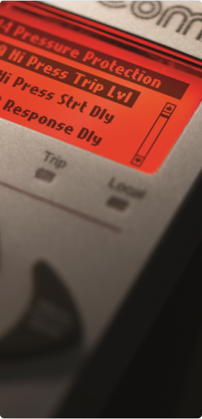
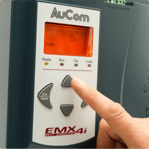
This system ensures ease of use with multilingual support, allowing users to switch between English, German, and Spanish interfaces. The standard LCD keypad features parameter classification and quick copying, enhancing reliability and user experience.
Features & Accessories
Starting Functions
- Constant current
- Current Ramp
Control Functions
- Rotational Speed Control (High and Low Speed)
- Pressure Control
- Position Control
- Synchron Motor Control
Stopping
- Coast to stop
- Soft stop
Protection
- Motor overload
- Overvoltage protection
- Undervoltage protection
- Phase loss
- Excess start time
- Phase sequence
- Current imbalance
- Motor thermistor
- Power circuit fault
- Supply frequency
- Instantaneous overcurrent
- Bypass overload
- Communications failure
Interface
- Fixed relay output (main contractor relay)
- Programmable relay (trip or run)
- Run relay output
Accessories (Optional)
- Remote operator
- Modbus
- Profibus
- DeviceNet
- PC Software
- Ethernet/IP
- Modbus TCP
- Profinet
Specifications
Mains Control Functions
Maximum Output Frequency |
599.00 Hz |
Carrier frequency |
7.5 kW and below: 2 kHz–15 kHz |
11 kW–93 kW: 2 kHz–10 kHz | |
110 kW–450 kW: 2 kHz–6 kHz | |
Automatic carrier frequency adjustment can be done according to the load characteristics | |
Input frequency resolution |
Digital setting: 0.01 Hz; analog setting: maximum frequency x 0.025 % |
Control mode
|
Asynchronous Motor: Open-Loop Vector (SVC), Closed-loop Vector (FVC), Torque Control, Voltage Vector Control (VVC) and V/F Control |
Synchronous/PM Motor: Open-Loop Vector (SVC), Closed-loop Vector (FVC), Torque Control, Voltage Vector Control (VVC) |
|
Synchronous Reluctance Motor: Open-Loop Vector (SVC), Closed-loop Vector (FVC), Voltage Vector Control (VVC) |
|
Starting torque |
SVC: 150 %; FVC: 180 % |
Speed regulation range |
SVC: 1:200; FVC: 1:1000 |
Speed stability accuracy |
SVC: ≤ ±0.5 %; FVC: ≤ ±0.3 % |
Torque response |
Torque step response < 20 ms |
Torque accuracy |
SVC: ±10 %; FVC: ±5 % |
Overload capacity |
150 % of rated current (60 s) |
Torque boost |
Automatic and manual torque boost modes are included |
V / F curve |
Multi-point V / F curve; 1.5-power V / F curve; square V / F curve |
Acceleration and deceleration curve |
Linear or s-shaped acceleration / deceleration modes: there are four groups of acceleration / deceleration time values Acceleration / deceleration time range: 0.00 s–600.00 s or 0.00 s–6000.00 s |
DC braking |
Start DC braking and shutdown DC braking are included (0.00 s–60.00 s) |
Jog control |
Jog frequency range: 0.00 Hz–599.00 Hz; Jog acceleration / deceleration time range: 0.00 s–600.00 s or 0.00 s–6000.0 s |
Tension control |
Four control modes are included: tension closed-loop speed mode, |
Multi-speed running |
Up to 16-speed running can be realized through terminals |
Built-in PID |
Can easily realize closed-loop process control |
Operation
Frequency sources |
Multiple frequency setting sources: operation panel setting, analog setting, control terminal setting, communication setting, etc. |
Auxiliary frequency sources |
Multiple auxiliary frequency sources: operation panel setting, analog setting, control terminal setting, communication setting, etc.; auxiliary frequency fine tuning and synthesis can be flexibly realized |
Universal terminals |
8 DI terminals (one high-speed terminal), three DO terminals 3 AI terminals (one supporting PT100), 2 AO terminals, 2 STO terminals |
Automatic acceleration / deceleration |
Automatic acceleration / deceleration time adjustment based on the load torque |
Product Standards
Applied safety standard |
IEC61800-5-1:2007 |
Applied EMC standard |
IEC61800-3:2005 |
EMC Filter |
All VFDs are built in line to IEC/EN 61800-3 category C3 |
Personalized Functions
Peripheral safety self-test |
A safety test is performed on the peripherals to timely identify any problems, such as a grounding problem or a short-circuit and improve the reliability of the system |
Common DC busbar function |
A common DC bus can be shared by multiple VFDs |
JOG key |
The JOG key on the operation panel can be used for jog running |
Fast current limiting function |
A quick current limiting algorithm is embedded to reduce the probability that an overcurrent fault happens to the VFD |
Motor parameter identification |
Automatic motor parameter identification |
Standardized panel extension cable |
A constant voltage output can be maintained in case of grid voltage variations |
Communication buses |
At least six kinds are supported (Modbus, Profinet, CANopen, Profibus-DP, EtherCAT and Ethernet) |
Expansion function |
I / 0 expansion card; bus communication expansion cards; PG cards (incremental sin / cos encoder cards) |
STO |
Safe torque off in case of emergency |
Inductors |
VFDs ≤ 45kW have no integrated inductors |
VFDs ≥ 55kW have an integrated DC inductor in the standard configuration |
|
VFDs ≥ 200kW an integrated output AC inductor can be selected as an option. |
|
For all H1-Series devices several types of external inductors are available on request. |
|
Braking Resistor |
VFDs ≤ 30kW have an integrated brake-unit in the standard configuration |
VFDs 37kW to 132kW an integrated brake-unit can be added as an option. |
|
For all H1-Series devices external break units are available on request. |
Environment
Use place |
Indoor, free from direct sunlight, dust, corrosive gas, flammable gas, oil mist, water vapour, dripping water or salt, etc. |
Altitude |
≤ 2,000 m ASL; 1 % current derating for every 100 m above 1000 m ASL The maximum application elevation is 3,000 m; when the elevation is higher than 3,000 m, contact the manufacturer |
Ambient temperature |
2 % derating for every 1°C above 40°C; > 50°C contact the manufacturer |
Humidity |
< 95 % (RH), w / o water droplets |
Vibration |
< 5.9 m/s2 (0.6 g) |
Storage temperature |
-20°C~+60°C |
Pollution degree |
No electrically conductive dust permitted. Cooling air must be clean and free from corrosive materials. Chemical gases, class 3C3. Solid particles, class 3S2. Painted circuit boards as standard. (according to IEC 60721-3-3) |
Display and panel operation protections and options
LCD display |
English, German and Spanish are supported |
LCD parameter copying |
Quick parameter copying can be accomplished on the LCD panel |
Protection functions |
Motor short-circuit detection Input / output phase loss protection Overcurrent protection Overvoltage protection Undervoltage protection Overtemperature protection Overload protection |
Options |
Brake assembly |