
WinMaster
Master soft start management
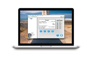
AuCom’s WinMaster is a user-friendly, comprehensive PC tool for managing the CSX and EMX4 series soft starters. WinMaster simplifies the control, monitoring, and programming of individual soft starters or entire networks, supporting up to 31 units within a single network.

Highlights
Network Management
Control up to 31 soft starters within a network or manage each starter individually. WinMaster also supports multiple networks, with functionality varying by model.
Operational Control
Enjoy streamlined operational control with options for Start, Stop, Reset, and Quick Stop commands.
Status Monitoring
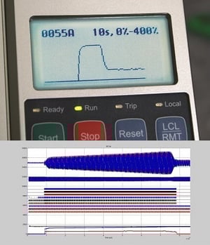
Monitor real-time status, including Ready, Starting, Running, Stopping, and Tripped states, for quick insights into system performance.
Parameter Management
Upload and download parameter settings effortlessly, enabling easy configuration across devices. Save network groups to file for efficient future access.
Download Start Here
Features & Accessories
Motor Control
- Dual motor set
- Constant current and current
ramp start - Current based torque control
- TVR start
- Kickstart
- Coast to stop and TVR stop
- Slip-ring motor control
- Emergency run
Human Interface
- Multi-language graphical display
- Starter status LEDs
- Date & time stamped event logging
- Real time performance graph
- Operational counters
- User programmable monitoring screen
- Fully customisable protections
- Customisable I/O operation
- Programmable start/stop
- User programmable metering screen
- Multi-level password protection
- Plug-in control terminal blocks
- Remote HMI
Advanced Diagnostics
- Internal wave form oscilloscope data logging
- Detailed event and trip logs
- Simulation modes
Protection
- Motor thermal model
- Motor thermistor
- Current imbalance
- Under/Overcurrent
- Under/over voltage
- Phase sequence
- Phase loss
- Power loss
- And more...
Input and Output Options
- Remote control inputs
(3 fixed, 2 programmable) - Relay outputs
(3 fixed, 3 programmable) - Analog output
(1 programmable) - Serial port (via comms module)
Accessories: Communication Options
- Modbus RTU
- Profibus
- DeviceNet
- Modbus TCP
- Profinet
- Ethernet/IP
- USB
Show more
Specifications
General
Current Range | 70 - 1700 A |
Supply
Mains Voltage (L1, L2, L3) | |
MVE-xxxx-V02 | 2.3 kV Phase-phase |
MVE-xxxx-V04 | 4.2 kV Phase-phase |
MVE-xxxx-V06 | 6.6 kV Phase-phase |
MVE-xxxx-V11 | 10/11 kV Phase-phase |
MVE-xxxx-V13 | 13.2-13.8 kV Phase-phase |
Control Voltage (A1, A2, A3) | 85 ~ 264 VAC or 90 ~ 350 VDC* |
Rated Frequency | 50/60 Hz |
Rated lightning impulse withstand voltage (Up) | |
2.3 - 6.6 kV
|
60 kV |
10/11 kV
|
75 kV |
13.2/13.8 kV
|
95 KV |
Rated short-time withstand current (symmetrical RMS) (lk) | 50 kA** |
Short Circuit Capability
Current Range | 24 A ~ 1250 A (nominal) |
Motor connection | In-line or inside delta |
Bypass | Integrated internal |
ANSI Protection Codes
Code | Description | Built-in Protection |
48 | Maximum start time | Excess start time |
66 | Too many starts | Restart delay and dynamic thermal model |
37 | Undercurrent | Undercurrent |
51L | Load Increase (alarm) | High current frequency output |
51R | Overcurrent - jam | Excess start time, electronic shearpin |
50 | Overcurrent - short | Shorted SCR, electronic shearpin |
49/51 | Thermal overload | Thermal overload - dynamic model |
46 | Current imbalance | Current imbalance |
27 | Undervoltage | Undervoltage |
59 | Overvoltage | Overvoltage |
47 | Phase loss | Phase loss |
47 | Phase sequence | Phase sequence |
50G | Ground fault | Ground fault |
85 | Communications failure | Communications failure |
85 | Internal failure | Internal failure |
94/95 |
Ext. fault 1/code-1 |
Auxiliary trip A |
Ext. fault 1/code-2 |
Auxiliary trip B | |
23 |
Motor overtemperature |
Thermistor protection* |
49 |
Stator winding overtemperature |
Thermistor protection* |
32 |
Under power |
Power Loss |
Inputs on Controller
Start (C23, C24) | 24 VDC, 8 mA approx |
Stop (C31, C32) | 24 VDC, 8 mA approx |
Reset (C41, C42) | 24 VDC, 8 mA approx |
Input A (C53, C54) | 24 VDC, 8 mA approx |
Input B (C63, C64) | 24 VDC, 8 mA approx |
Motor thermistor (B4, B5) | Trip point > 2.4 kΩ |
Outputs
Rating of output relays on Controller | 10 A @ 250 VAC resistive |
6 A @ 250 VAC 15 p.f. 0.3 | |
10 A @ 30 VDC resistive | |
Outputs | |
Relay output A (41, 43, 44) | Normally Open |
Output Relay B (51, 52, 54)
|
Changeover |
Output Relay C (61, 62, 64) | Changeover |
Analog output (B10, B11)
|
0-20 mA or 4-20 mA |
Environmental
Degree of Protection | |
Power Assembly | IP00 |
Controller | IP54 / NEM12 |
Operating Temperature | |
Humidity
|
5% to 95% Relative Humidity |
Storage Temperature | -25 °C to +70 °C |
Humidity
|
5% to 95% Relative Humidity |
Operating Altitude | 1000 m ASL, higher with derating |
Pollution Degree | IP00 |
Vibration | Designed to IEC 60068 |
Equipment Class (EMC) | Class A |
EMC Emission | IEC 60947-4-2 |
EMC Immunity | IEC 60947-4-2 |
Certification
CCC | GB 14048.6 |
CE | EN 60947-4-2 |
C-UL | C22.2 No. 60947-4-2 |
UL | 60947-4-2 |
Marine | |
Lloyds | Lloyds Marine No 1 Specification |
ABS | Steel Vessel Rules 2010 |
RCM |
IEC 60947-4-2
|
Show more